Static electromagnetic generators of Clemente Figueras, Robert Holcomb, Park Jae-Sun and Shoji Haneda.
I assumed that Clemente Figuera (a Spanish engineer) sold another patent to the world bank, which is unknown to us. We know of only two patents from 1902 (the time of Figuera's sale of the invention rights). One with a closed loop of a magnetic wire, and the other for amplifying the magnetic field for a moving conductor. I reflected all my thoughts on this subject in the open publication CLEMENTE FIGUERA GENERATOR 1902. In the same publication I assumed that there is another possible working version, which was built, by analogy with electric dynamos and electric generators of that time. We take a photo of a dynamo and an electric alternating current generator from an exhibition of the late 19th century.
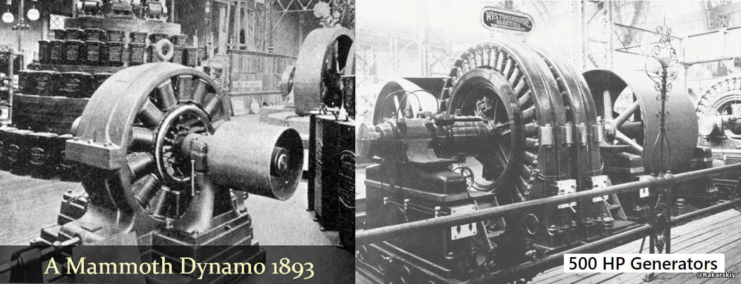
As you can see, the excitation coils were attached to the stator steel yoke. The poles of the excitation coils of the permanent electromagnets were oriented to the axis of the armature on which the generator windings were made. To connect to the load of the lead, the following was produced: DC machines through a collector and removable copper brushes, and for AC machines through current collector rings. This was common practice for dynamo and alternator designs of the time: static excitation and a dynamic armature with phase windings.
During the construction of the Niagara Hydroelectric Power Plant, a new type of generator with an external magnetic field rotating "Umbrella type" was used, designed by the Scottish electrical engineer Gurney Forbes. Buffalo's Early Electrification — ETHW Niagara Falls Energy Project (1888) - Open Tesla Research
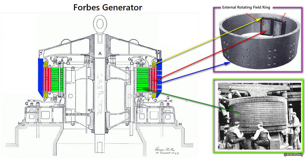
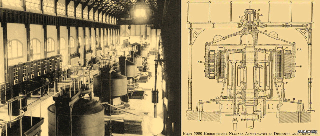
The Forbes generator had an internal fixed stator with grooves for laying the wires of the two phases of the generator, around which electromagnets with metal cores attached to an iron yoke rotated.
US518945A - Dynamo-electric machine - Google Patents
The copper-carbon brushes invented by Forbes made it possible to switch the excitation currents of electromagnets (the invention is still used today). The main thing is the design solution, which the engineer Figuera knew about and could admit as an engineer, that if you perform not the physical rotation of permanent electromagnets, but control the switching on and off of electromagnets, it is possible to obtain a rotating magnetic field. The only condition is what order must be built in the electromagnet system to avoid the transformer effect. Obviously, when Figuera created the machine without rotation, he was already aware of the differences between the operation of a transformer and a generator. The task was to ensure the excitation of a constant field in the magnetic system of the generator and move it between the phase wires for EMF induction.
What is the danger of such a decision of engineer Clement Figuera for the energy lobby of electricity sellers? Most likely, the types of generators of that time could be transformed into a static generator machine without much alteration by making a mechanical switching unit. Such a decision, if it had information dissemination, would make an explosion in electricity generation. It is for this reason that the cost of the project was so high. We do not know all the details, the purchase of the sale, whether the engineer received the declared amount, the fact remains. In 1908, Figuera again applied for a patent for a static generator machine. The engineer did not live to see the publication, we do not know all the details that he wanted to state and whether what was published in the patent is true. There can be many options for using the declared electromagnet switching unit. Try to transfer what is indicated in the patent to the previously considered version of Dynamo at the end of 19. Engineer Figuer's decision should be rational and simple. At the same time, the fact of the actual construction of such a generator in the Spanish Canary Islands is stated in the publications of that time.
At the end of the second decade of the 21st century, Robert Holcomb, M.D., designed and built an electromagnetic generator without rotating parts. In the United States, he received a patent [valid until 2038]for his invention, which is essentially identical in principle of operation to another patent for a static rotary generator, by Korean author Park Jae-sun [valid until 2030]:
US20190238011A1 (US11336134B2) - Solid state multipole and single-pole electric generator rotor for AC/DC power generators.
KR1020090062765A (US8629588B2) - Apparatus for generating AC power by a DC power brush rotating with a field pole generator and apparatus for generating DC electricity.
The difference between the two patented systems is only in the implementation of the control of the excitation of the magnetic rotor with switchable electromagnets magnets. The rotor core itself is without mechanical movement. In Robert Holcomb - through the appropriate software control and an electronic semiconductor key controller. In Park Jae-Sun, control is carried out through a collector-brush unit, but unlike traditional DC machines, in the author's version, the anchor is static, and the brushes rotate around the collector, the design additionally includes slip rings and another pair of brushes.
The version described in Park Jae-Sun's patent could presumably have been implemented by engineer Clementi Figuera.
The issue of the operability of this technology does not raise any objections. A very flimsy design, made by a garage craftsman like Park Jae-Sun's patent, demonstrated a self-propelled system, in a closed loop with a rechargeable battery.
The video can be viewed at [ Electromagnetic generator over unity ].
I examine these patents and how they work in more detail in the publication: Electromagnetic generator, without rotation of the magnetic rotor in self-propelled mode. | Patreon
In addition to the two patents claimed, there is another earlier one, by the Japanese inventor Shoji Haneda: [ JP3847740B2 ] 発電装置 - Equipment for the generation of electricity.

This patent both reveals the entire operation of both a mechanical and a solid (static) electromagnetic generator using the example of a simpler design.


The EPC induction in the generator winding occurs only at the same distance of the conductor as it is induced in the middle of the magnetic circuit. This completely corresponds to the EPC formula of the transformer. Magnetic power lines of magnetic flux do not overflow (overflow) the conductor.
E = 2πΦf / √2 = 2π(Φ = ∆B*S)f / √2 ; at the moment (2π/√2=4.44) - E = 4.44 Φ f
This formula is derived from the self-induction formula, i.e. the induction of an emf on a conductor from a change in magnetic flux in a ring core. Although it is called a transformer formula, it has nothing to do with the action of mutual induction between the primary and secondary windings. In the literature, unfortunately, this formula is directly associated with the operation of a transformer, which absolutely does not correspond to the action of mutual induction, but only to self-induction, when the transformer operates in the reverse mode. EMF Equation of Transformer
If we look at the design of the simplest electromagnetic oscillator that is in any textbook, on the basis of which Shoji Haned, patents his idea with a static rotor and a simple stator, you will see that the magnetic field cannot cut the wires of the phase winding. What is the principle of the EMF in the core window on the conductor? This principle is stated as the Toroidal moment.
Magnetic toroidal moment and its relation to the magnetoelectric effect. The presence of a magnetic toroidic dipole moment T in condensed matter is due to the presence of a magnetoelectric effect: Application of a magnetic field H in the plane of a toroidal solenoid leads via the Lorentz force to an accumulation of current loops and thus to an electric polarization perpendicular to both T and H. The resulting polarization has the form Pi = εijkTjHk (with ε being the Levi-Civita symbol). The resulting magnetoelectric tensor describing the cross-correlated response is thus antisymmetric.
If we look at the magnetic excitation fluxes from the rotor and the phase current strength, they coincide in the generator (add up). In theory, this should also happen in the transformer. In the picture below, I assumed that they also add up in the transformer.
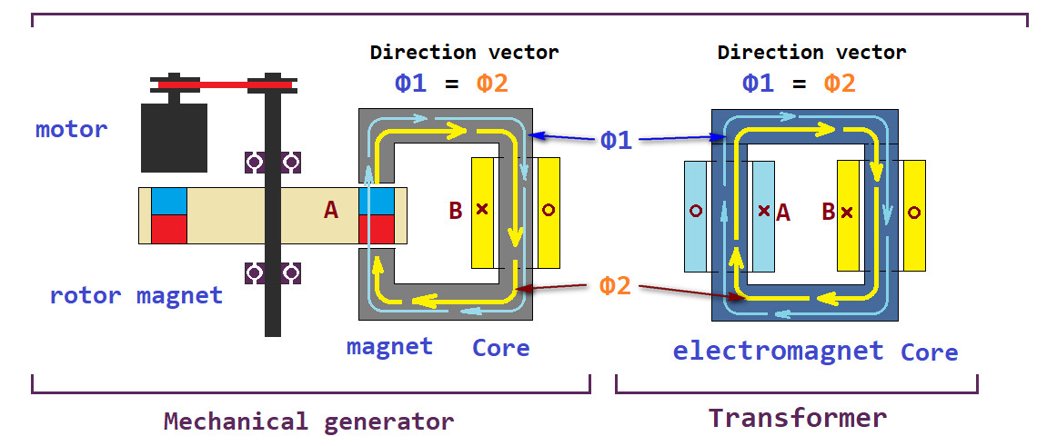
In reality, the alternating excitation current in the transformer induces a magnetic flux in the core. But the current of the secondary winding in the transformer is opposite to the excitation current and does not affect the magnetic field of the core in any way. The magnetic field of the core will correspond to the magnetic field of the primary winding of the transformer. If you instead of a magnetic rotor put a variable electromagnet in the design of the simplest generator, you will get the simplest transformer, whose output winding will be connected with interturn flux linkage and energy transfer from the primary circuit to the secondary. Although in electrical engineering there is a transformer formula for EMF E = 4.44fΦm [ E1/N1 = E2/N2 = 4.44fΦm ], it works in a transformer only partially during flyback operation of the transformer converter. We need to get a generator and level the process of mutual induction between the winding of the variable electromagnet and the secondary winding.
No generator has excitation by means of a variable electromagnet. Either a permanent magnet or an electromagnet with a constant regulated current is used.
EMF in the generator phase winding occurs with a change in magnetic induction in a closed magnetic circuit of the Dynamic toroidal dipole. This is achieved by switching the magnetic flux between the magnetic rotor and the stator iron. Or simply by correspondingly closing the magnetic circuit in generators with magnetic flux switching.


If you look at the rotor cross-section with the stator of an electromagnetic generator, you can see the gap between the rotor poles and the number of slots in the stator. You will see that for a three-phase machine, the number of slots will coincide with the laying of the wires of one phase. (In the figure, I marked it as the focus of an important magnetic circuit)
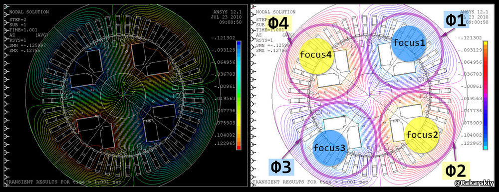
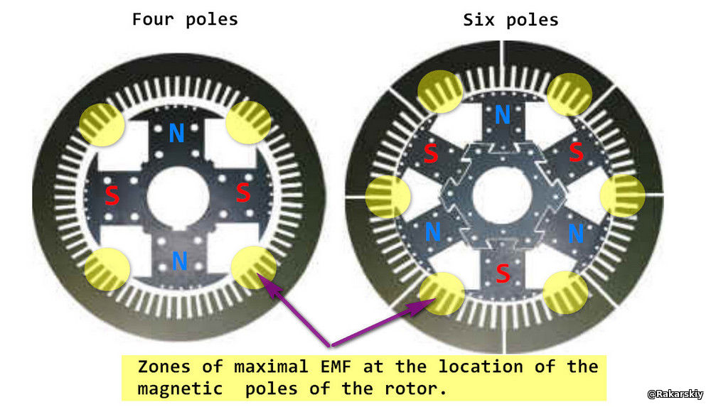
I believe that I have shown you quite convincingly the very essence of how generators are designed and why a variable electromagnet cannot perform the role of an exciter of the generator's magnetic field. The question remains to consider how Dr. Holcomb solved this problem in his machine.
Let's ask ourselves, how will the rotation of the excited field in the anchor of a DC motor differ? What will happen if we rotate not the anchor with the collector, but the brushes around the collector?
It is obvious that the magnetic poles on the edges of the anchor core will move depending on the commutation of the anchor windings. Thus, if we lock the commutation and rotate the anchor itself, we will get the same effect of rotation of the magnetic poles of the anchor. The golden rule of mathematics is "the sum does not change from changing the places of the terms".
This commutation, with a certain step, cross-winding of coils which provides a constant magnetic induction on the plane of the anchor pole, is suitable for the motor. The guy also launched an analog-replication of the generator, according to the Park Jae-sun patent, with a regular anchor of a constant motor and a specially wound stator with nine separate phases. The guy demonstrated that such a concept is working.
Electromagnetic generator, without rotation of the magnetic rotor in self-propelled mode. | Patreon
Unfortunately, the guy does not continue his research, but I can conclude that a standard DC motor rotor is not the best solution for a generator of this design. The first primary excitation of the magnetic field must provide sufficient magnetic induction to induce idle running of the EPS in the phase windings. From this point on, we must understand that a good motor is usually a bad generator, and a good generator is usually a bad motor. Yes, theoretically and practically they are reversible, but there are many conditions for the discrepancy between technical capabilities. So in the case of this guy, in order to get at least some result, he wound about 200 turns on one phase, with wires of 0.4 mm in diameter. This is more of a motor winding than a generator. The wire itself has low capabilities for CURRENT STRENGTH and total wire length, high current resistance. The golden rule of the generator - the winding resistance should tend to zero - is violated. The reason was precisely the low starting magnetic induction of the idle running, which was formed by the anchor design. Probably, the guy needed to determine the maximum possibilities of field excitation in the anchor, and on the basis of the obtained data calculate the phase cross-section and the current strength capabilities.
The peculiarity of generator excitation from an electromagnet is that when current arises in the phase, the anchor excitation current will decrease. This effect was obtained by another replicator, on the basis of the calculated data obtained from this experiment. This confirms the conclusion that the system is in the generator mode, and not the conversion mode on mutual induction. Experiments confirmed the functionality of the claimed design according to Park Jae-sung's patent.
Let's consider a possible design of Clemente Figuera's generator, which he built in the Canary Islands, the design of which was sold.
Let's return to Robert Holcomb's systems in his Holcomb Center in the USA, you can see various working models live. The peculiarity of these patents or patent applications is that each, in fact, has a demonstration model. Moreover, some generators are installed to provide energy both to the Holcomb Center itself and to a third-party commercial facility. To believe or not to believe is not a question for us. Data from the energy supplier shows that this device works as a power amplifier. Self-propelled operation of the system has not been publicly demonstrated, but this does not mean that such a mode, as the authors claim, is impossible.
Let's look at the patent application (for the US) of Robert Holcomb:
Full text and figures in PDF format.
The proposed design of the generator in the application/patent with two rotors and a double stator is similar to the design of a similar motor.
Let's return to the design features of the Forbes generator installed at the Niagara Dam when Clemente Figuera was still alive. The engineer was absolutely aware of such design features, which were at that time in the specialized press (see photo above).
If we take the outer rotor and the part of the stator with which it interacts, from the design of Robert Holcomb, we will see a similar magnetic system of the Forbes generator, only with a physically rotating rotor. In its advertising videos, the Holcomb Center demonstrates the rotation of the magnetic poles of the outer stator, only without physical rotation.
Let's say we are at the beginning of the twentieth century and we need to organize switching of rotor electromagnets through a collector-brush unit using an external drive motor. This solution was used in motor anchors at that time. We have 16 electromagnets with four electromagnets per separate pole.
Let's take a diagram of a DC motor anchor with 16 coils and 16 lamellas. Two counters from a DC source are connected to the collector. This anchor forms two poles, due to the fact that the current flows in half of the coils in one direction, and in the other half - in the opposite direction. We add two more brushes and divide the coils into four sections, thereby organizing the polarization of the anchor into four poles. This is how large and powerful DC motors with four poles work. Again, such a solution was already used in the time of engineer Figueire.
Thus, engineer Figuere had to calculate the excitation currents and develop an algorithm for laying the phase wires of the generator to obtain the maximum induction of the EMF and current for the corresponding load. The engineer only had to find a suitable design of a dynamo or DC motor, convert the anchor into a stationary stator and make an electromechanical switching unit. If we recall how Nikola Tesla converted a DC dynamo at the Edison plant into an AC generator, replacing the collector lamellas with slip rings and changing the anchor winding to a phase closed to these rings. A truly ingenious solution by Figuera (who made the excitation electromagnets switch, move the field in the magnetic system of the alternator, without physically moving the machine parts of the rotor (anchor) / stator, and scared the energy lobby.
The question arises, why did no one think of making this version of the alternator in the early 20th century (except Figuera), and in the following years, up to the Japanese Shoji Haneda patent of 2006 "JP2004140991A - Generator"? Is this a century-old engineering shortsightedness? What is surprising is that the brilliant persistence of Dr. Robert Holcomb, M.D., not only made it possible to declare the operability of this system without physically rotating the generator parts, but also to manufacture solid-state generators in various variations, forcing them to work in the OverUnity mode. This fact put the scientific community with the constant that an electromagnetic mechanical generator is a converter of mechanical energy into electrical energy, in a very awkward position.
Bravo, Dr. Holcomb, you have overturned a century-old constant of classical physics.
This is just my guess about the possible configuration of the generator without rotating parts from 1902 by the Spanish engineer Clemente Figuera, for the burial of whose technology the World Bank agreed to pay the equivalent of 320 kg of gold (at the time of sale - 60 million pesetas). I am used to basing my research only on logic, technical capabilities and achievements of that time. Engineers design and build their creations only on real effects, even if they contradict what physicists take as a basis. It was a time of brilliant solutions (inventions) in electrical engineering, when civilization was becoming electric.
----------------------------
Figuera could not disclose the details of the technology he sold, it was a matter of honor. In the following years it became obvious that the buyers were not going to give a go to this progressive technology. The engineer Clemente Figuera had another version of a static converter generating more power than needed for excitation, which was probably not built and demonstrated, as bought by the world bank. Probably this was the reason for trying to disclose the features of another system that Figuera had in his baggage of solutions. Unfortunately, the engineer himself did not live to see the publication of the 1908 patent Patent 44267 "Figuera Generator" . Whether it was a natural death or forced, we do not know and probably will never know. Constantino de Buforn Jacas, Figuera's partner, published several patents, which fundamentally describe the device of a resistive controller that controls the remagnetization of two solenoids connected by one magnetic circuit (47706, 50216, 52968, 55411 and 57955). I managed to explore this engineering problem, which echoes another engineering solution - the end of the 20th decade of the 20th century. I published all my thoughts and discoveries in my book:
ANAPOLE MOMEN and ELECTROMAGNETIC GENERATOR
You can do everything yourself, it is easy to start the rotation of magnetic poles in the anchor of a DC motor inserted into the stator and even get generation. But to make a practically working model to provide your garage, you will have to delve into the engineering art of electromechanical design, electrical circuit design, etc. I have prepared material where I tried to explain everything in simple language and made a calculation of the simplest original model. All you have to do is follow the calculation data: order a core, order or make an electronic controller to control the switching of the electromagnetic "anchor", wind the windings according to the appropriate algorithm, make a rectification unit and battery charger. You will get your generator with a magnetic rotor that does not rotate.
Motionless ALTERNATOR / Нерухомий АЛЬТЕРНАТОР / ALTERNADOR estacionario | Patreon


